![]()
![]()
![]()
![]()
|
|
|
|
|
When arriving at the VOIs sub-page a fusion image is shown to the left which is composed of the Mag and the FLOW MASK (Angio) images. Note the two panels A and B in the upper right which correspond to those images, and the slider for mixing the respective contributions in the fusion image.
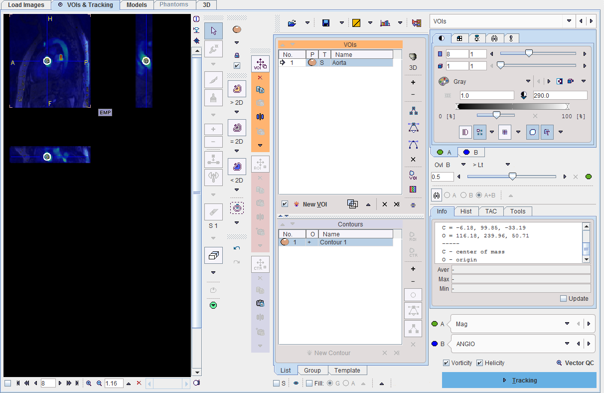
In the lower right, the A and B images can be redefined.
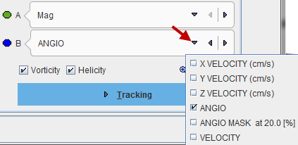
The choices are
VOI Definition
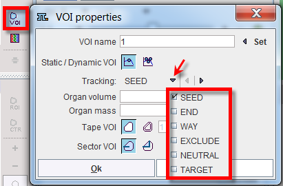
The calculation of streamlines is based on VOIs which can play different roles:
VOIs can be created with the usual PMOD VOI tools. When creating a new VOI, a dialog window pops up which requires defining the appropriate Tracking property. Later on, this property can be changed using the VOI properties functionality as illustrated below.
Note the check boxes Vorticity and Helicity. If they are checked, PGEM calculates parametric maps called Vorticity Amplitude and Absolute Helicity, respectively. Vorticity is a measure of rotation, whereas helicity relates to the knottedness in fluids, and they can be used for assessing the degree of flow non-laminarity.
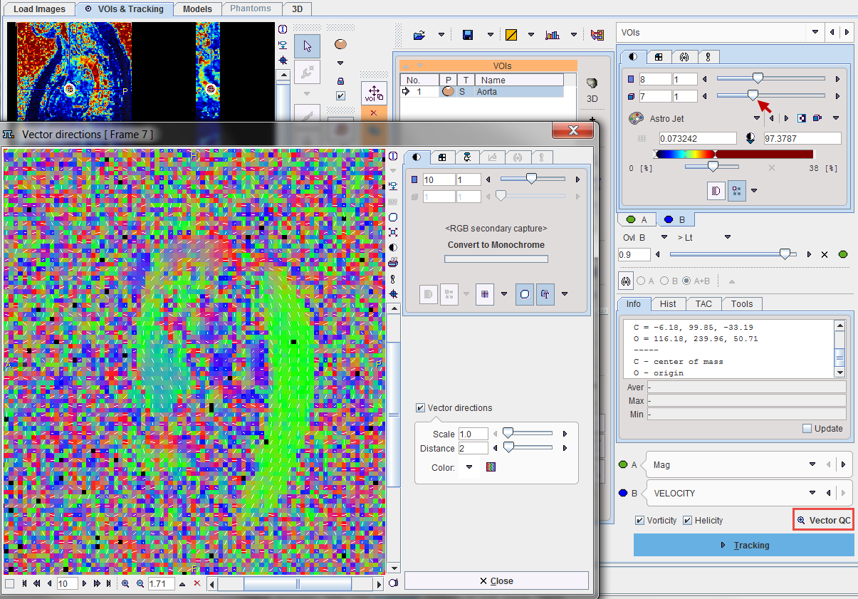
Vector Inspection
The loaded velocity vectors can be inspected with the Vector QC button. It shows a window with the projection of the flow direction vectors together with a color-coded direction image. Red indicates diffusion along the x-axis (left-right), green diffusion along the y-axis (posterior-anterior), and blue diffusion along the z-axis (inferior-superior).
Note that the time frame has to be selected before starting Vector QC, as the velocity vector field is four-dimensional.
Please proceed with the ![]() button in the lower right.
button in the lower right.