![]()
![]()
![]()
![]()
|
|
|
|
|
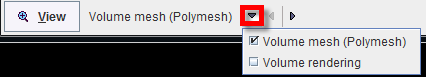
The  button allows displaying the results of the CFD case selected in the list in a 3D window. There are two options for visualization of the CFD results: as Polymesh or as Volume rendering:
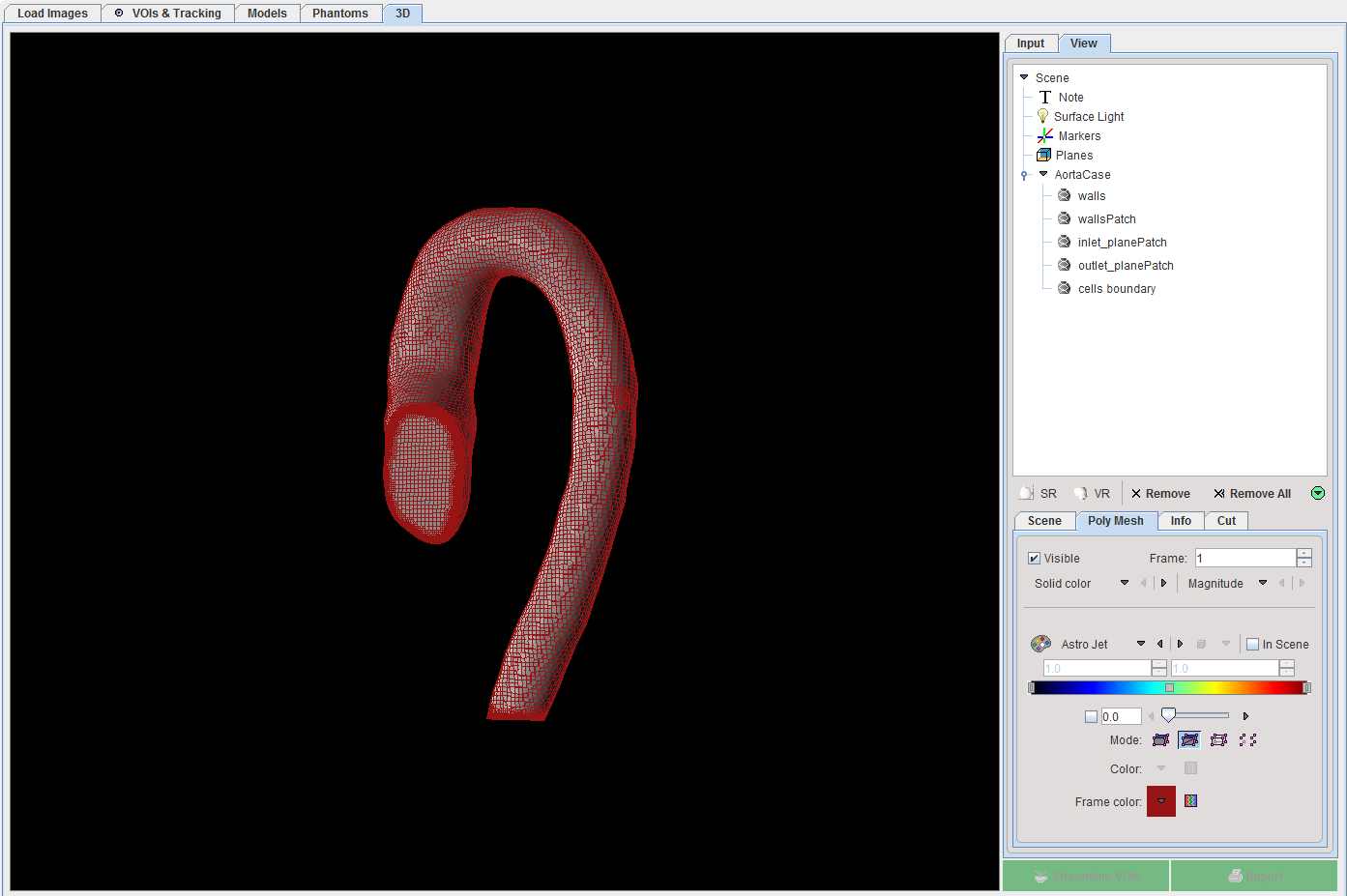
Visualization of the CFD Results as Polymesh
Select the Volume mesh option in the list and activate the View button to transfer the CFD results to the 3D page. The result is illustrated below:
Visualization of the CFD Results as Volume Rendering
With the Volume rendering selection additional settings are available, as illustrated below:
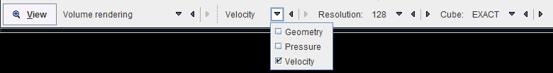
The settings are summarized in the following table:
|
Allows selecting which of the CFD results is initially shown as a texture on the volume render mesh: Velocity, Pressure or Geometry. |
|
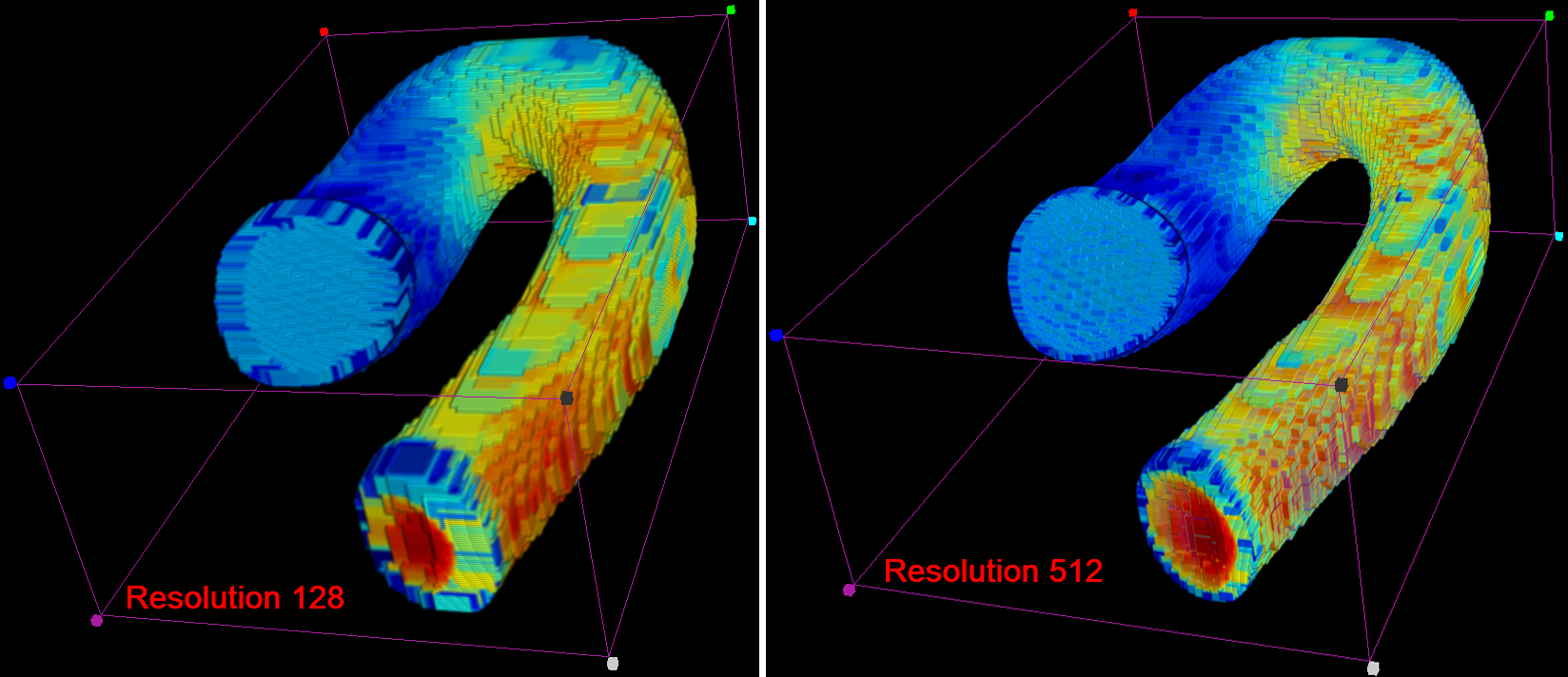
Allows setting the image resolution. The following selection is available: 64, 128, 256 and 512. The selected number indicates how many cubes will be rendered in each direction. Each cube stores the information about the variable field from one cell of the volume mesh. The higher the resolution the better the precision, but the memory requirements grow significantly. The rendering results for two different resolution(128 and 512) and the same Cube size are illustrated below:
|
|
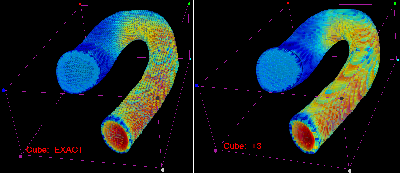
Allows setting the size for the Cube to be displayed or not (NONE) in the 3D page:
With the EXACT selection each cube will be placed in one voxel of the 3D image. When one of the other options is selected, +1, +2 or +3 each cube will be placed in one voxel and in 1/2/3 neighbouring voxels. The rendering results for two different Cube size (EXACT and +3) and the same Resolution are illustrated below:
|
Note:
In the 3D scene the cubes will be drawn in the positions which represent the centers of the volume mesh cells. The number and sized of the cubes can be changed using the Resolution and the Cube settings.
The following settings were used for visualization:
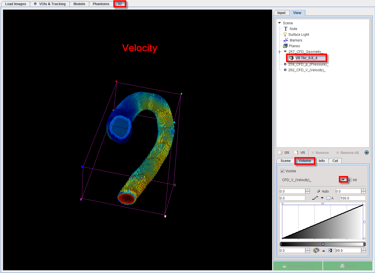
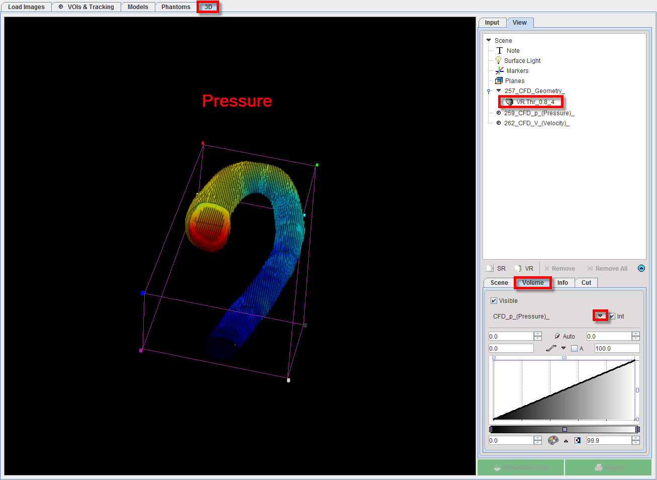
The simulation results are transferred to the 3D page activating the View button. They are available as images on the Input tab of the 3D page. In the View tree, the CFD_Geometry is available as the volume render object, the CFD_p_(Pressure) and CFD_V_(Velocity) as images for the texture.
The two physical variables, velocity and pressure, are visualized as textures on the same geometry as illustrated below:
In addition, plane elements can be defined for composing a meaningful scene. The planes serve for defining the parts to be cut out of a VR object.
Please refer to the PMOD 3D Rendering Tool Users Guide for any further information about the rendering.