![]()
![]()
![]()
![]()
|
|
|
|
|
The 3D interface for the definition of the cutting planes is illustrated below:
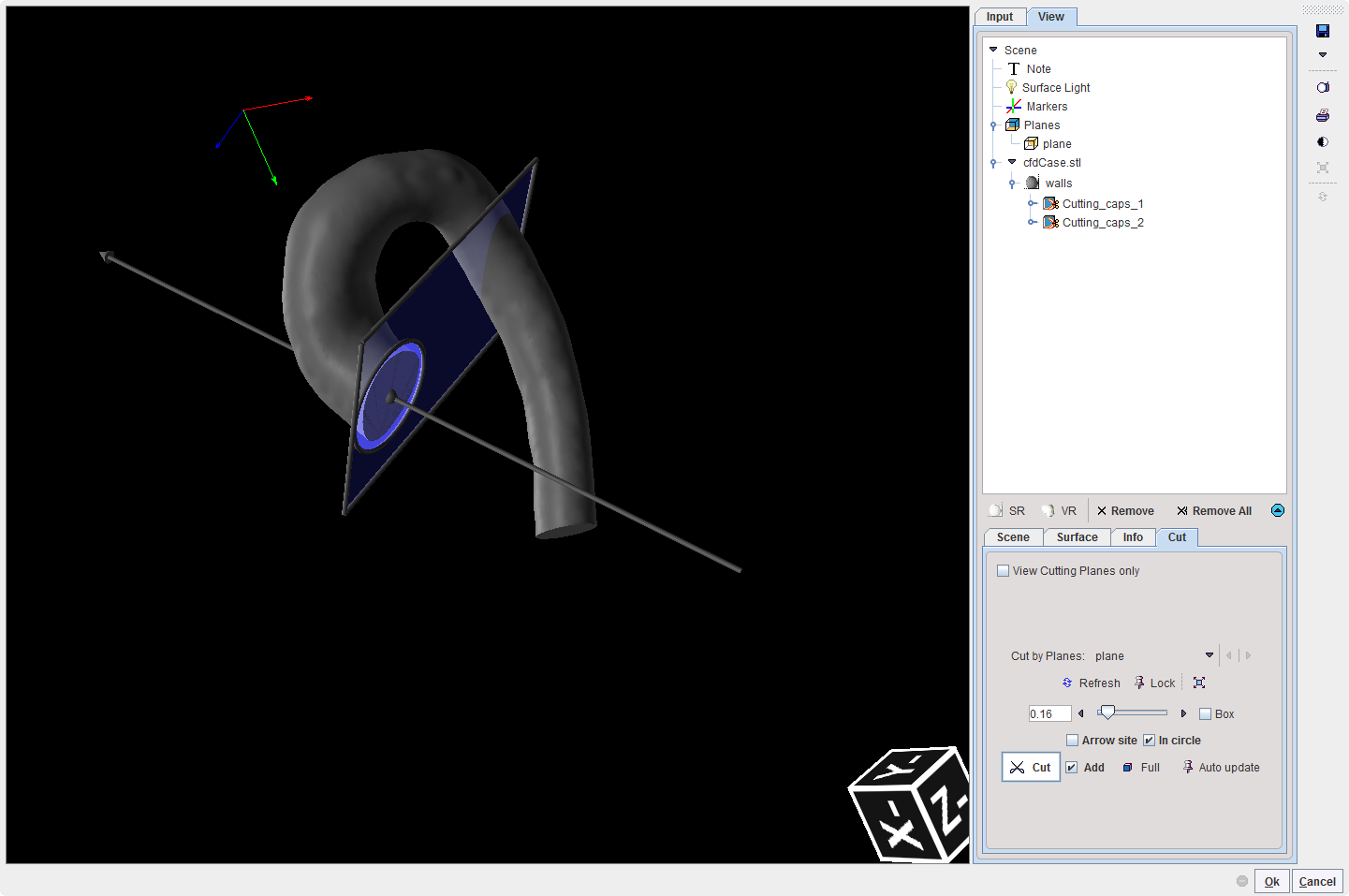
In the example above one oblique plane was used to create the cutting planes on the selected surface render object: the walls. The results are two entries in the View tree, in the walls branch: the Cutting_caps_1 and Cutting_caps_2.
Close the 3D interface with the OK button to generate the surface mesh. The calculation process may take a couple of minutes. The results are shown in a 3D window as illustrated below:
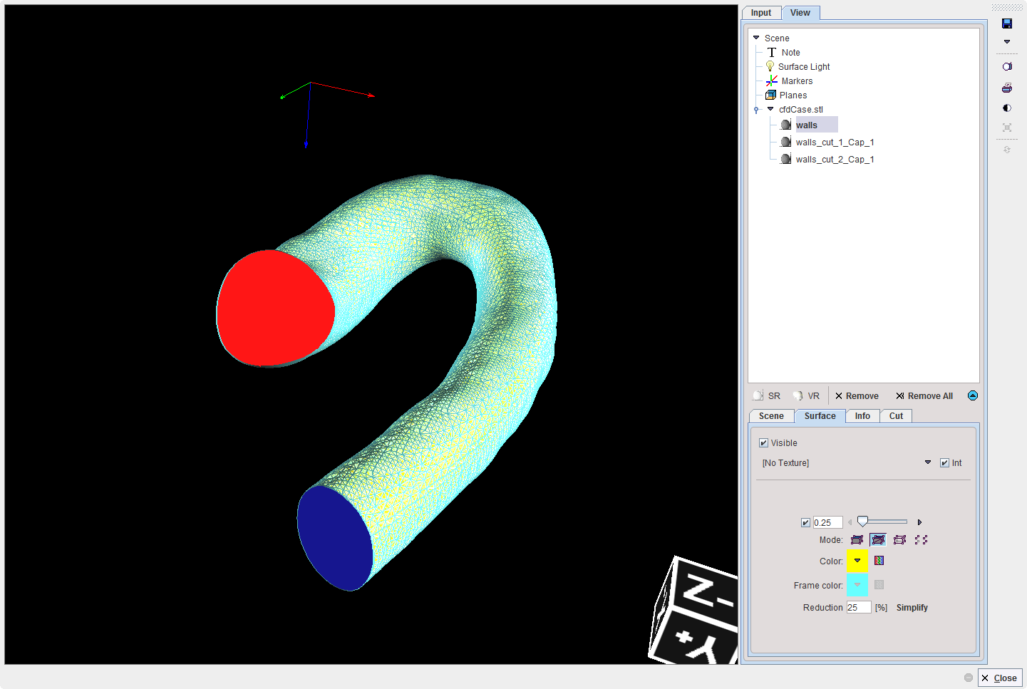
The 3D interface allows exploring interactively the generated surface mesh. Close the window and continue with the VM creation. The cutting planes will be used to define the boundary conditions for the CFD simulation.