The result of the brain structure transformation is shown on the BRAIN SEGMENTS page. The image on the BRAIN SEGMENTS tab is the transformed atlas with integer labels as the pixel values. It is fused with the MR image.

Result Space
There are three different options to evaluate the PET image, which can be configured using the Result space radio button. The information visualized on the page is updated as soon as the configuration is changed. The image display shows the MR image transformed to the selected result space together with the brain structures.
The Result space options are:
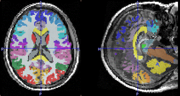
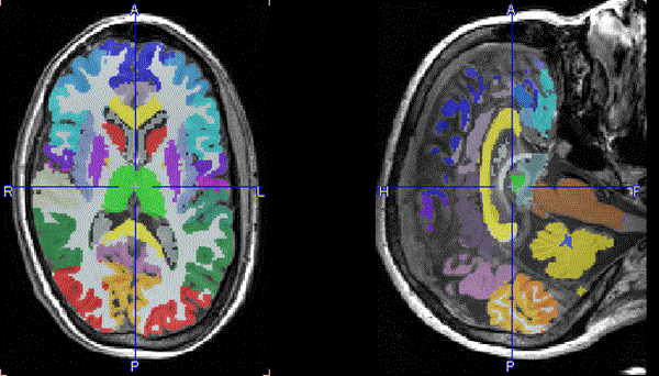

Sulci Deformation
The Sulci deformation option instructs the program to perform an anatomical optimization of the VOIs. Based on the MR image, the VOI boundaries are adjusted such that the border should essentially follow the sulci bottoms.
Intersection of the Atlas Structures with Gray Matter
The original atlas structures may not be restricted to the gray matter part of the whole brain. Users can take advantage of the gray matter probability to restrict the structures to pixels with a high probability of belonging to gray matter. This masking is controlled by the elements in the Mask by area.
There is a choice between two types of probability information:
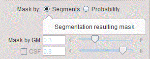
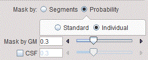
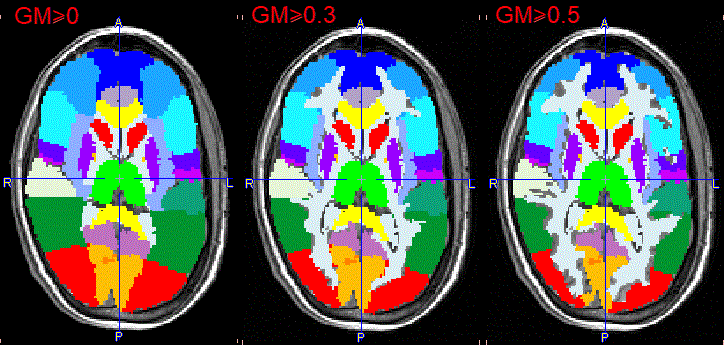
The GM threshold slider of Probability masking allows defining the lower threshold applied to the GM probability map for creating the mask. The higher the threshold value, the thinner the cortical structures become. With the CSF box enabled, the CSF threshold slider allows trimming further the GM mask: the higher the threshold the thicker the cortical structures become.
The illustration below shows individual masking at three increasing GM probability thresholds while the CSF box is disabled. The Standard mask will result in broader structures at the same probability threshold.
The illustration below shows individual masking at three decreasing CSF probability thresholds and a constant GM probability threshold of 0.5. The Standard mask results in narrower structures as CSF probability threshold decreases.
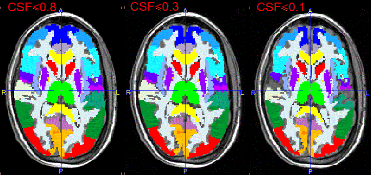
Note that the central structures are not affected by masking in the example above, because the box Mask non-cortical regions is not enabled. If the option is enabled, the central structures are also shrinking, as illustrated below. However, because of the low probability levels in that area, the reduction may become too severe. Therefore, masking outside the cortex will usually remain disabled.

Intersected VOIs and Partial Volume Correction (PVC)
VOI-based PVC correction methods only work properly when all the activity contained in the brain is included in VOIs. Therefore, in the case of VOI masking, PNEURO will automatically create the complementary VOIs, i.e. the VOIs masked with the gray matter pixels below the threshold, as well as the CSF pixels. These complementary VOIs will be used for the PVC calculation, but will not be visible in the user interface and in the result statistics.
Structure Outlining
Once the result space and gray matter masking have been specified, the brain structures are fully defined and can be outlined to create contour VOIs. This process is started with the Outline action button.