![]()
![]()
![]()
![]()
|
|
|
|
|
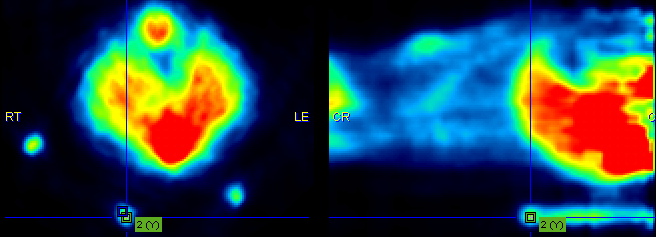
If the automatic matching rigid matching is not working properly for a combination of images, the use of fiducial markers should be considered. In the example below three capillaries filled with activity were attached to the bed of the mouse, and then imaging performed on separate CT and PET systems. The capillaries are clearly visible in the CT, whereas the activity in the inner of the capillaries is picked up by PET. The tubes were plugged by a small plasticine plugs, which can be seen by zooming in on the CT image. Consequently, the end of the capillary activity in PET should correspond to end of the plug in CT.
For marker matching, the user explores the two image sets and marks corresponding locations, i.e. markers. A transformation is then calculated which brings the two spatial arrangements of markers into optimal agreement.
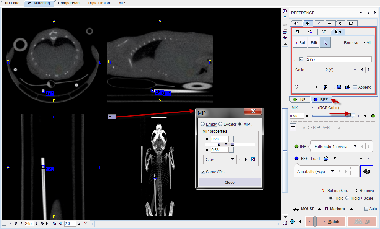
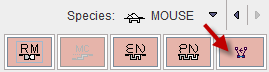
Please first load the input images on the INPUT sub-page and make sure the Species setting is correct. Proceed with the markers matching button.
On the REFERENCE sub-page load the reference image with the REF: Load button. Next start landmark definition with the Set markers button.
Marker Definition for the Reference
 define the behavior when clicking into the image. With Set active, each click into the image generates a marker. With Edit active, markers can be dragged to different locations. The third button is the neutral mode for triangulating the images until the marker position has been found.
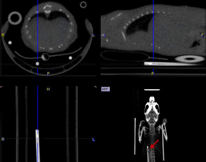
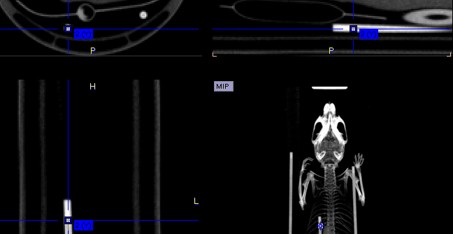

Marker Definition for the Input
The next task is the definition of the corresponding landmarks for the input image.
Matching Parameters
As the image content is not used for the registration, only parameter is whether the transformation is strictly rigid, or whether a scaling is allowed (Rigid + Scale option). The Auto option enables immediate registration as soon as markers are defined.
![]()
Starting Markers Matching
Please use the Match button to start the registration of the two sets of landmarks.