![]()
![]()
![]()
![]()
|
|
|
|
|
Supervised clustering is based on the specification of a set of TACs which represent the average time course in specific tissues. Typically, these kinetic class TACs are generated using a representative set of PET series which are segmented by a different means, e.g. by using the anatomical information in matched MR series [6,7]. For use in PSEG it is assumed that the kinetic class TACs are already available as one file per TAC.
Note: If the class TACs have been created using z-score normalized data, the image series to be segmented also has to be normalized before loading into PSEG.
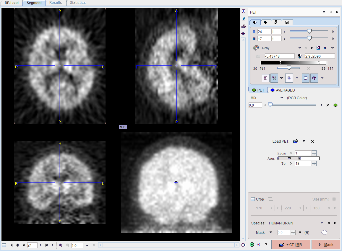
Image Loading
Use Load PET for loading the image series to be segmented. The example below illustrates the situation after loading a [11C]PIB scan which has been z-score normalized. This process results in negative numbers, which are evident in the lower colorbar threshold.
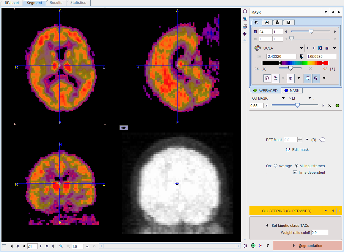
Masking
After configuration of the mask and proceeding with Mask to the MASK page, the segmentation method can be switched to CLUSTERING (SUPERVISED).
Kinetic Class TACs Definition
Set kinetic class TACs opens a dialog window for specifying the kinetic class TACs. In the illustration below C1 corresponds to normal grey matter, C2 to specific binding, and C3 to the blood pool similar to Fig. 1 in [7]. Note the normalized curve shapes which are very different from normal uptake TACs.
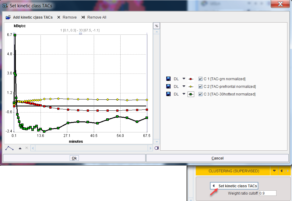
Add kinetic class TACs opens a dialog window for selecting the curves, either from a database as below, or via Load from File System from the disk. Retrieve adds the selected curves to the panel. Curves can be discarded by selecting them to the right and use Remove, or Remove all.
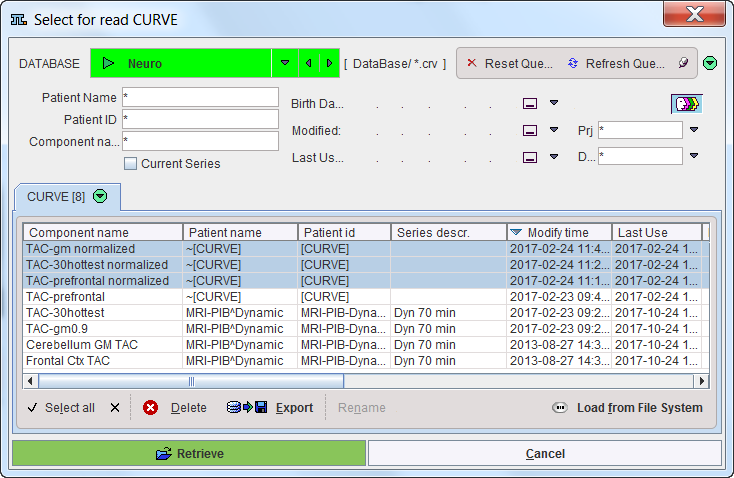
Note that the selection is serialized during subsequent uses of CLUSTER ANALYSIS (SUPERVISED).
Segmentation
Segmentation starts the the classification procedure. For each pixel in the mask it finds the optimal linear combination of all kinetic class curves so that all coefficients are non-negative (NNLS, non-negative least squares). It then assigns the pixel to the class with the highest coefficient (or weight), if its ration to the sum of all coefficient is greater than Weight ratio cutoff.
The resulting segment image is shown on the SEGMENTS page, and the segments can be converted into VOIs using the Outline Maps button.
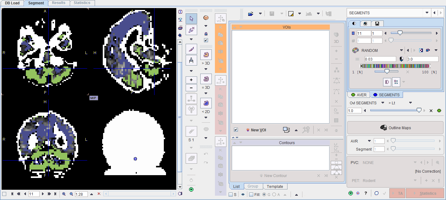
The VOIs created by the segment assignment process are regular PMOD contour VOIs which can be adjusted in many ways. For instance, if the segmentation produced two complementary parts of a structure, their VOIs can easily be merged into a single VOI.
Manual VOI Addition
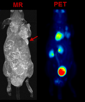
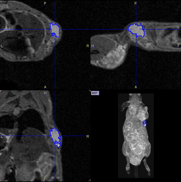
VOIs can also be added in a completely manual manner. In the example data set, for example, there is a bright part in the MR image which does not take up FDG.
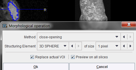
In the present situation, a VOI can be obtained from the MRI image using the iso-contouring tool as illustrated below. First, the MR image tab is selected to direct the iso-contouring operation to the MR image content, not the SEGMENTS. Then, the iso-contouring is started. The parameters are set to 3D with Multi regions off, to create a single compact VOI. Setting the Mode of searching to From cursor will ensure that VOI creation starts at the location where the user clicks. The iso-contour is shown in the image, and the contouring level may be adjusted by the Threshold setting.
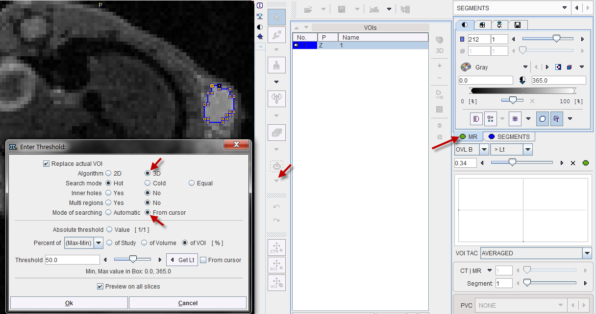
After closing the dialog window with Ok, the contouring result is shown as illustrated below, and the VOI can be labeled.
Morphological Operations
Morphological operations support convenient functions for modifying the created VOIs, such as shrinking, growing, removing holes and single pixels. Please select the VOI to be modified in the list, then activate the Erosion/Dilation function from the VOI tools area.
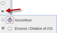
A dialog window appears which offers a list of Methods with corresponding Structuring Elements and their size. The changes to the VOI are immediately reflection when configuring the operation. Note that the result may replace the existing VOI, or added as a new VOI.
Non-overlapping of VOIs
In order to avoid the overlapping of VOIs, which causes problems with the partial-volume correction, the VOI Edit mode is pre-configured accordingly.
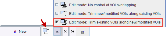
If VOIs are created by the merging of existing VOIs, please make sure that the original VOIs are removed.
Palette of VOI Tools
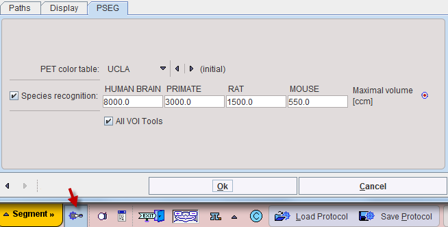
Per default only a subset of the PMOD VOI tools is available in PSEG. To be able to use the full VOI functionality please enable All VOI Tools in the configuration.